Other basic structures of secondary demoulding
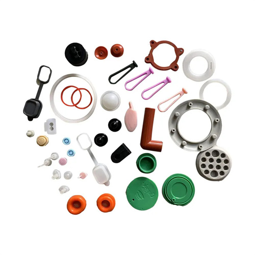
A secondary ejection mechanism is a specialized structure used in injection molds to address issues such as molded parts remaining stuck or deforming after primary ejection. In addition to the common ejector plate and ejector pin composite structure, a variety of other basic structural forms exist. These structures utilize different operating principles and combinations to meet the demolding requirements of various parts. The core of a secondary ejection mechanism is to achieve two orderly demolding actions. The first ejection pushes the part a certain distance from the mold cavity, breaking the tight fit between the part and the cavity. The second ejection completely disengages the part from the ejection mechanism, ensuring it can be dropped or removed by a robotic arm. Understanding the characteristics and applicable scope of these basic structures is crucial for mold designers to select the appropriate demolding solution.
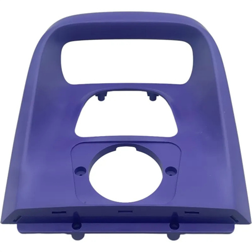
The rocker-type secondary demolding mechanism utilizes the rotational motion of a rocker to achieve a double demolding action. Its simple structure and reliable operation make it suitable for demolding small and medium-sized plastic parts. The mechanism primarily consists of a rocker, an ejector pin, an ejector tube, and a return spring. One end of the rocker pin contacts a pin on the fixed mold base, while the other end is connected to the ejector tube or ejector pin. During the mold opening process, when the movable mold and fixed mold separate to a certain distance, the rocker pin rotates, driving the ejector tube for the first demolding operation, ejecting the part 5-10 mm from the cavity. As the mold opening continues, the rocker disengages from the pin and returns to its original position under the action of the return spring. At this point, the ejector pin, driven by the ejection mechanism, performs a second demolding operation, completely ejecting the part from the ejector tube. The advantage of the rocker-type secondary demolding mechanism is that it requires no additional drive device and relies solely on the mold opening and closing motion to achieve double demolding, resulting in low cost. However, its disadvantage is that the rocker pin’s fixed motion trajectory limits its adjustment range. It is therefore suitable for parts with low demolding resistance and relatively simple shapes, such as small shells.
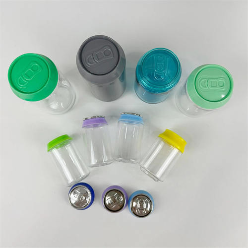
The pull-plate-type secondary demolding mechanism uses a pull plate to switch between two demolding operations. It features high demolding force and adjustable stroke, making it suitable for large or complex-shaped plastic parts. This mechanism primarily consists of a pull plate, a pull rod, an ejector plate, an ejector pin, and a stop pin. The pull plate is fixed to the fixed mold base plate. One end of the pull rod is connected to the pull plate, and the other end is connected to the ejector plate on the movable mold side. During the initial mold opening, the pull plate pulls the rod, driving the ejector plate for the first demolding operation, ejecting the part a certain distance from the cavity. When the ejector plate reaches the stop pin position, the first demolding operation ends, the pull plate separates from the pull rod, and the ejector mechanism continues to drive the ejector pin for the second demolding operation, fully ejecting the part from the ejector plate. The advantage of the pull-plate-type secondary demolding mechanism is that the stroke of the two demolding operations can be precisely controlled by adjusting the position of the stop pins, adapting to the demolding requirements of parts of varying heights. Furthermore, its rigid connection provides strong demolding force, making it suitable for large parts or those that fit tightly within the ejector mechanism. For example, in the mold of a large plastic barrel, the use of a pull-plate secondary demolding structure can effectively solve the adhesion problem between the plastic part and the top plate.
A spring-loaded secondary mold release mechanism utilizes the elastic force of a spring for the first demolding step, followed by an ejector mechanism for the second demolding step. Its compact design and rapid response make it suitable for applications requiring minimal demolding resistance and requiring rapid demolding. The mechanism primarily consists of a spring, ejector tube, ejector pin, and spring seat. The spring is installed between the ejector tube and the movable mold base plate, while the ejector pin passes through the center hole of the ejector tube. When the mold is closed, the spring is compressed. When the mold is open, the spring’s elastic force pushes the ejector tube to eject the part from the cavity, completing the first demolding step. Once the ejector tube has moved a certain distance, the ejector mechanism activates, pushing the ejector pin for the second demolding step, ejecting the part from the ejector tube. The advantages of a spring-loaded secondary mold release mechanism include the elimination of complex transmission mechanisms, compact design, and low cost, making it suitable for molds with limited space. However, the spring’s elastic force diminishes over time, affecting the consistency of the first demolding step. Therefore, the spring needs to be replaced regularly. This mechanism is suitable for smaller production runs or for parts with less stringent requirements for demolding consistency, such as small toys and electrical components.

The inclined guide pin-type secondary demolding mechanism uses the guiding action of inclined guide pins to achieve the transition between the two demolding operations. It features high motion precision and accurate control, making it suitable for plastic parts requiring high demolding accuracy. The mechanism primarily consists of inclined guide pins, sliders, ejector pins, ejector plates, and guide channels. The inclined guide pins are fixed to the fixed mold base plate, while the sliders are mounted within the guide channels of the movable mold, allowing for diagonal movement. The sliders are connected to the ejector plates by a connecting rod. During mold opening, the inclined guide pins drive the sliders along the guide channels, which, via the connecting rods, push the ejector plates for the first demolding operation. When the sliders reach the end of the guide channels, the first demolding operation is complete, and the ejector mechanism activates, pushing the ejector pins for the second demolding operation. The advantages of the inclined guide pin-type secondary demolding mechanism include precise guidance from the inclined guide pins, ensuring the sequence and stroke accuracy of the two demolding operations, and avoiding interference. Furthermore, the inclined angle of the inclined guide pins can be customized to adjust the stroke and speed of the first demolding operation. This structure is suitable for precision plastic parts with high requirements for demoulding accuracy, such as optical lenses, electronic connectors, etc., and can effectively ensure the dimensional accuracy and surface quality of plastic parts during the demoulding process.
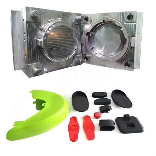
The lever-type secondary demolding mechanism utilizes the amplifying effect of a lever to achieve two demolding operations. It features high demolding force and flexible stroke, making it suitable for large, thick-walled, or irregularly shaped plastic parts. This mechanism primarily consists of a lever, a fulcrum, a push block, an ejector plate, and a stop block. The lever rotates about the fulcrum, with one end contacting the push block on the fixed mold and the other end connected to the ejector plate on the movable mold. During mold opening, the push block pushes one end of the lever, causing it to rotate about the fulcrum. The other end of the lever pushes the ejector plate for the first demolding operation. When the ejector plate reaches the stop block, the first demolding operation is complete, the lever disengages from the push block, and the ejector mechanism continues to push the ejector plate for the second demolding operation. The advantage of the lever-type secondary demolding mechanism is that the amplifying effect of the lever allows for a high demolding force with a relatively small driving force, making it suitable for plastic parts with high demolding resistance. Furthermore, by adjusting the length ratio of the lever and the position of the fulcrum, the stroke and force of the two demolding operations can be flexibly adjusted. This structure has been widely used in molds for large automobile bumpers, washing machine inner drums and other plastic parts, effectively solving the demolding problem of large plastic parts.
Different secondary demolding structures have their own characteristics and scope of application. When selecting a secondary demolding structure, mold designers should consider factors such as the part’s size, shape, material properties, and production batch size to ensure that the selected structure meets the part’s demolding requirements while also balancing mold manufacturing costs and production efficiency. With the advancement of injection molding technology, secondary demolding structures are constantly being innovated and optimized. For example, composite structures combining hydraulic and pneumatic drive methods further enhance demolding flexibility and precision, providing more reliable technical support for the production of complex plastic parts.