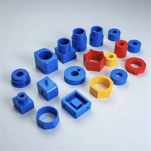
Assembly of injection molded locating ring
The injection molding locating ring is a crucial component connecting the injection molding machine to the mold. Its primary function is to ensure accurate installation and positioning of the mold on the machine, ensuring precise alignment of the mold’s sprue bushing with the machine’s nozzle, allowing the molten plastic to enter the mold cavity. Improper assembly of the locating ring can cause the mold to shift, potentially causing wear on the sprue bushing and plastic leakage. In more serious cases, it can affect the dimensional accuracy of the molded part and even damage the machine and mold. Therefore, assembly of the injection molding locating ring is a critical step in the preparations for injection molding production and must be performed strictly in accordance with operating procedures to ensure accurate and reliable assembly.

The assembly of an injection molding locating ring must first ensure that the fit between the locating ring and the mold meets design requirements. The locating ring is typically bolted to the mold’s fixed die plate. A transition fit (e.g., H7/k6) should be used between its outer diameter and the mounting hole in the mold fixed die plate to ensure that the locating ring’s axis aligns with the mold’s axis. Before assembly, the locating ring’s dimensional accuracy and surface finish should be checked to ensure that its outer diameter tolerance and end face flatness meet standards. This will prevent assembly deviations caused by quality issues with the locating ring itself. The mounting holes in the mold fixed die plate should also be cleaned and inspected to remove burrs, oil, and impurities. A feeler gauge should be used to check the hole diameter to ensure the clearance with the locating ring is within the allowable range. For example, for a 100mm diameter locating ring, the mounting hole diameter should be within 100±0.03mm to ensure smooth installation without noticeable looseness.
The fit between the locating ring and the injection molding machine’s locating hole is also a key aspect of the assembly process that requires special attention. The injection molding machine’s template typically features locating holes whose dimensions match the outer diameter of the locating ring. A clearance fit (e.g., H7/g6) is typically used between the two to facilitate mold installation and removal while ensuring accurate positioning. Before assembly, the diameter and depth of the injection molding machine’s locating holes must be measured to ensure they match the dimensions of the locating ring. If the locating holes are severely worn, resulting in an excessive clearance between the locating ring and the locating ring, this will affect the mold’s positioning accuracy and require repair or replacement of the locating hole. When installing the mold, align the locating ring with the injection molding machine’s locating hole and slowly lower the mold to ensure the locating ring fits smoothly into the locating hole. Avoid forcing the locating ring or hole, which could damage it. After installation, check the mold’s positioning accuracy with a dial indicator to ensure the axis of the mold and the axis of the injection molding machine deviate by no more than 0.05mm.
The securing method and tightening torque of the retaining ring have a significant impact on assembly quality. Retaining rings are typically secured to the mold’s fixed die plate using hexagon socket or cylindrical head bolts. The number and specifications of the bolts should be determined based on the retaining ring’s size and the mold’s weight. Generally, retaining rings with a diameter greater than 100 mm should be secured with at least four bolts, evenly distributed around the circumference of the retaining ring. When tightening the bolts, tighten them evenly and diagonally to avoid deformation or shifting of the retaining ring due to uneven force. The tightening torque should be determined based on the bolt’s specifications and material. For example, the tightening torque for M10 high-strength bolts ( grade 8.8 ) is typically set between 30 and 35 N · m . Excessive torque may cause the bolt to break or deform the retaining ring, while insufficient torque may loosen the retaining ring, affecting positioning accuracy. After tightening, check that the end face of the retaining ring is firmly seated against the mold’s fixed die plate. Use a feeler gauge to check the gap to ensure it does not exceed 0.03 mm.
During assembly, attention must also be paid to the fit between the locating ring and the sprue bushing. The locating ring typically has a through-hole in its center to accommodate the head of the sprue bushing. The two should be coaxial, with a coaxiality error within 0.02mm, to ensure precise alignment between the injection molding machine nozzle and the sprue bushing. Before assembly, check the diameter of the locating ring through-hole and the diameter of the sprue bushing head to ensure an appropriate clearance (typically 0.05-0.1mm) to avoid deformation of the sprue bushing due to an interference fit. Furthermore, the end face of the locating ring should be flush with or slightly lower than the end face of the sprue bushing (no more than 0.1mm) to prevent the locating ring from interfering with the contact between the injection molding machine nozzle and the sprue bushing. After assembly, manually rotate the injection molding machine nozzle to check for smooth alignment with the sprue bushing and for any signs of binding or misalignment.
Post-assembly inspection and adjustment of injection molding retaining rings are the final steps in ensuring assembly quality. First, perform a visual inspection to verify that the retaining rings are installed smoothly, free of skew or deformation, and that all bolts are complete and tightened. Second, use a dial or micrometer indicator to measure the mold’s positioning accuracy. Fix the base of the indicator to the injection molding machine’s template, with the needle touching the edge of the mold’s fixed die plate. Slowly rotate the mold (for rotatable molds) or move the injection molding machine’s template to measure the mold’s radial runout. The error should not exceed 0.05mm. Finally, perform a trial mold verification. By injecting a small amount of plastic, observe the uniformity of the plastic at the gate and any signs of leakage or burrs to determine the accuracy of the retaining ring assembly. If any problems are found, the retaining ring should be removed, re-inspected, and re-assembled until it meets the requirements. Only by ensuring the assembly quality of the injection molding retaining rings can a reliable foundation be established for subsequent injection molding production, ensuring the quality of the plastic parts and the stability of production.