Hot runner injection mold
Hot runner injection molds are specialized molding tools that integrate a hot runner system. By adding heating and temperature control components to traditional molds, they achieve continuous melting of the melt within the runners. They are the core technology behind hot runner injection molding. Their basic structure includes a cavity, core, hot runner plate, nozzle, heating device, temperature control system, and cooling system. These components work together to ensure stable melt flow and precise part formation. Compared to traditional cold runner molds, hot runner molds eliminate the cooling mechanisms of the main and branch runners. Instead, they utilize a heated hot runner plate and nozzle, ensuring that the melt temperature within the runners remains within the desired molding range (e.g., 190-220°C for PP and 240-270°C for PA66). For example, a hot runner mold for producing plastic bottle caps, with its 16-cavity structure, evenly distributes the melt across the cavities through the hot runner plate, achieving a molding time of just 4 seconds per mold, significantly faster than the 8 seconds required for traditional cold runner molds.
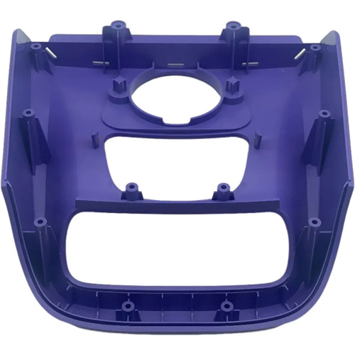
One of the core components of a hot runner injection mold is the hot runner plate, which distributes the melt evenly from the main channel to each nozzle. The runner design directly affects the uniformity of the melt flow. The runner cross-section is usually circular, with a diameter calculated based on the melt flow rate, generally 8-15mm, to ensure that the melt flow resistance is small and the runner is full. The runner layout needs to be symmetrical. Common forms include H-type, X-type, and radial type. The H-type is suitable for symmetrical distribution of an even number of cavities, and the radial type is suitable for multiple cavities arranged in a circular pattern (such as bottle cap molds). The hot runner plate material must have good thermal conductivity and heat resistance. P20 steel or H13 steel is commonly used, and the surface is nitrided (hardness ≥50HRC) to enhance wear resistance. Large hot runner plates also require guide posts and locating pins to ensure precise fit with other mold components to avoid displacement caused by thermal expansion.
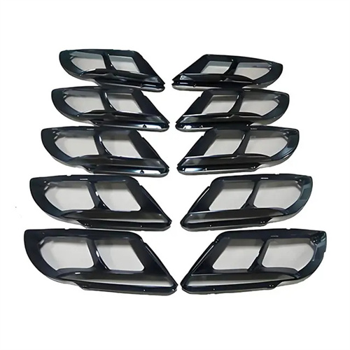
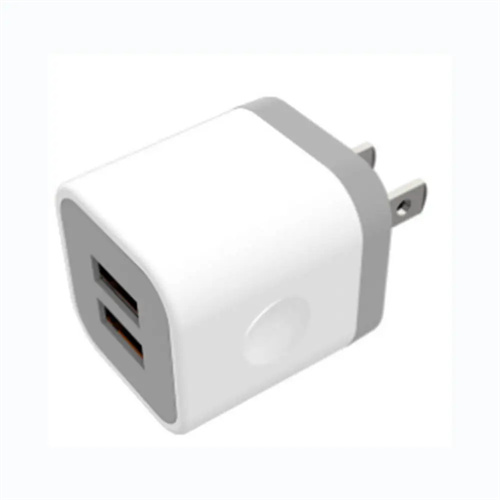
The nozzle system is a key actuator in hot runner molds, responsible for conveying the melt from the hot runner plate to the mold cavity. Its design is selected based on the requirements of the molded part. Open nozzles offer a simple structure and low cost, making them suitable for small and medium-sized parts, but they also produce a larger gate mark (0.5-2mm in diameter). Valve nozzles, which control the gate opening and closing via a needle valve, eliminate gate marks and are suitable for parts requiring high surface quality (such as automotive exterior trim). However, their structure is complex and their cost is 30-50% higher. The connection between the nozzle and the hot runner plate must be reliably sealed, typically using a threaded connection with an O-ring seal to prevent leakage. The contact area between the nozzle tip and the mold cavity must be insulated to prevent excessive heat transfer, which could cause localized heating in the cavity and affect part cooling. For example, molds for producing transparent PET preforms use a pointed hot nozzle with a tip diameter of only 1mm, ensuring minimal gate marks and smooth filling.
The heating and temperature control system is the heart of the hot runner mold, determining melt temperature stability. The heating system consists of a heating coil, a heating rod, and a heating plate. The heating coil wraps around the outside of the nozzle, while the heating rod is embedded in the hot runner plate. The power density is calculated based on the heated area and is typically 5-15W/cm². The temperature control system utilizes PID (proportional-integral-differential) control, with each heating zone equipped with an independent thermocouple and thermostat. This allows for control accuracy of ±1°C, preventing local overheating and material degradation. For large hot runner plates, zoned heating is required. For example, the plate can be divided into a center zone and an edge zone, each with its own thermostat to compensate for differential heat loss. For example, in an eight-cavity hot runner mold, the hot runner plate is divided into four heating zones. Independent temperature control is used to maintain a temperature difference within 2°C between zones, ensuring even melt distribution.
Hot runner injection mold design must balance functionality and reliability. Runner dimensions must be optimized through CAE simulation to ensure that the flow time difference between each branch is ≤0.5 seconds and the pressure drop difference is ≤5%. For glass fiber reinforced plastics, runners must avoid sharp corners and use rounded corner transitions with a radius of ≥3mm to reduce fiber breakage and nozzle wear. The cooling system design must balance hot runner heating with cavity cooling. An insulating layer (such as a 0.5mm thick mica sheet) should be installed between the hot runner plate and the cavity, while dense cooling channels (spacing ≤30mm) should be arranged around the cavity to ensure rapid part set. Mold material selection must match the operating temperature. Pre-hardened steel (such as 718H) should be used for the cavity and core, and heat-resistant steel (such as S136) should be used for hot runner components to prevent deformation at high temperatures. Furthermore, leak-proof structures should be implemented, such as a stepped seal at the interface between the nozzle and the hot runner plate, or a self-sealing nozzle that automatically strengthens its seal under injection pressure.