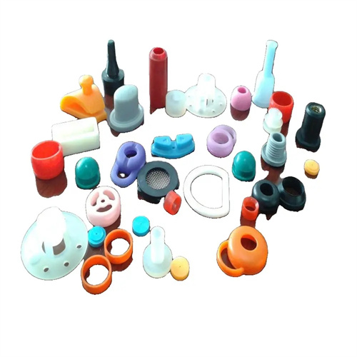
Relationship between plastic part wall thickness and cooling time
The relationship between part wall thickness and cooling time is a core principle in the injection molding process, directly impacting production efficiency and part quality. The underlying logic is that increasing wall thickness leads to a nonlinear increase in cooling time. Because plastics have low thermal conductivity (typically 0.1-0.3 W/(m・K) ), the time it takes for heat to transfer from the center of the part to the surface increases significantly with increasing wall thickness. Cooling time accounts for approximately 50-70% of the entire molding cycle and is a key factor in determining production efficiency. For example, a PP part with a 2mm wall thickness takes approximately 10 seconds to cool, while the same part with a 4mm wall thickness takes 30 seconds, rather than a simple doubling of the time . This nonlinear relationship stems from Fourier’s law of heat conduction, which states that heat transfer time is approximately proportional to the square of the wall thickness (cooling time ∝ wall thickness² / thermal diffusivity). Therefore, properly designing wall thickness is crucial for shortening cycle times and reducing costs.
The mechanism by which wall thickness affects cooling time can be analyzed through the heat conduction process: After the melt fills the mold cavity, heat dissipates through the cavity walls. The surface layer of the plastic part first cools and solidifies, forming a solid shell. Over time, the solidified layer gradually advances toward the center, until the center temperature drops below the material’s heat distortion temperature (e.g., approximately 100°C for PP), completing the cooling process. For thin-walled parts (wall thickness ≤ 1mm), the solidified layer can quickly penetrate the entire cross-section, resulting in short and uniform cooling time. However, for thick-walled parts (wall thickness ≥ 3mm), the long heat dissipation path in the center can easily lead to “core overheating.” Even after the surface layer cools, the core may remain molten or highly elastic, requiring longer to fully solidify. For example, for a 5mm-thick PC part, the surface layer cools to 120°C in 15 seconds (PC has a heat distortion temperature of 130°C), but the center temperature takes 60 seconds to drop from 300°C to 130°C. The actual cooling time should be based on the center temperature.
The calculation method of cooling time needs to be combined with the wall thickness and material properties. The commonly used empirical formula is: cooling time = (wall thickness²×K ) / (π²×α), where K is the safety factor ( 1.2-1.5 ), α is the material’s thermal diffusivity ( m²/s ). The value of α varies significantly among different materials. For example, PE ‘s α is ≈ 1.2×10⁻⁷m²/s , while PC ‘s is ≈ 0.8×10⁻⁷m²/s . Therefore, for the same wall thickness, PC ‘s cooling time is 50% longer than PE’s . For example, to calculate the cooling time for a 3mm thick PE part, substituting the formula into ( 0.003²×1.3 ) / ( 3.14²×1.2×10⁻⁷ ) ≈ 22 seconds, which is consistent with the actual production average of 20-25 seconds. For more accurate calculations, mold temperature, melt temperature, and cooling water path layout must be considered. CAE simulations should be used to analyze the temperature distribution and determine the minimum cooling time to avoid part warping or dimensional instability caused by insufficient cooling.
Properly designing the wall thickness of plastic parts can effectively shorten cooling time and improve production efficiency. However, it’s important to avoid extreme wall thicknesses of either too thin or too thick. Excessively thin wall thickness (e.g., ≤0.5mm) results in high melt flow resistance, making filling difficult and requiring higher injection pressure and temperature, which can actually extend the cycle time. Excessively thick wall thickness (e.g., ≥10mm) results in prolonged cooling times (often exceeding 2 minutes) and is prone to defects such as sink marks and bubbles. Optimal wall thickness design should adhere to the principle of “uniform and appropriate.” Wall thickness variations within a part should not exceed a 3:1 ratio (e.g., maximum wall thickness 3mm, minimum wall thickness ≥1mm) to avoid internal stress caused by uneven cooling rates. Minimum wall thickness should be determined based on material flow (e.g., ABS has a minimum wall thickness of 0.8mm, while PE can go up to 0.5mm) to ensure smooth filling. For example, optimizing the wall thickness of a particular part from 5mm to 3mm (while maintaining structural strength) reduced cooling time from 60 seconds to 25 seconds, increasing production efficiency by 140%.
Process optimization can compensate for the effect of wall thickness on cooling time within a certain range. Key measures include strengthening the cooling system and adjusting process parameters. Dense cooling channels are placed in thick-walled areas, with a channel diameter of 0.5-0.8 times the wall thickness (e.g., 3mm channels for a 5mm wall thickness) and a center-to-center distance of 2-3 times the diameter to ensure cooling efficiency. Conformal channels (e.g., 3D printing) are used to conform to the contours of the part, shortening the cooling distance in thick-walled areas by 30-50%. Increasing the cooling water flow rate (from 1m/s to 2m/s) enhances convective heat transfer and reduces the temperature difference between the mold and the part. Adjusting process parameters can include lowering the melt temperature (e.g., from 220°C to 200°C for PP), increasing the holding pressure (to compensate for thick-wall shrinkage), and employing stepped cooling (rapid initial cooling followed by slower cooling later). For example, the cooling time of a thick-walled PA66 plastic part (wall thickness 8mm) was shortened from 150 seconds to 90 seconds by adding conformal water channels and increasing the water flow rate, while also eliminating sink mark defects.