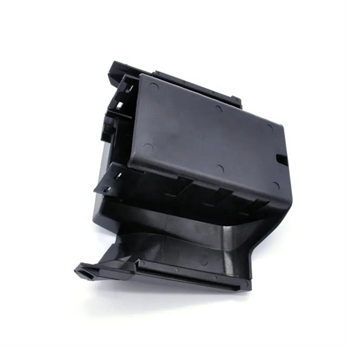
A dual-ejection mechanism for injection molding is a complex mold structure that enables simultaneous or step-by-step ejection of a plastic part from both the cavity and core. It is primarily used in situations where the part’s clamping force on both the cavity and core is high, and unidirectional ejection can easily cause deformation or damage. This includes deep-cavity box-shaped parts and cylindrical parts with inner flanges. Its core principle utilizes two independent ejection systems (typically cavity-side ejection and core-side ejection) to apply ejection force in a predetermined sequence, releasing the part from one side first and then the other. This prevents defects such as warping and cracking caused by excessive force on one side. For example, when producing a 100mm-deep plastic cup lid, the inner wall’s clamping force on the core is similar to the outer wall’s adhesion to the cavity. Ejection solely through the core can cause the lid’s edges to tear. With a dual-ejection mechanism, a push plate on the cavity side first pushes the lid out 10mm, followed by an ejector pin on the core side, increasing the yield rate from 75% to 99%.
The structure of a dual-ejection mechanism typically consists of an active ejection system, a passive ejection system, and a sequential control device. These components must work precisely together to achieve orderly operation. The active ejection system is often an ejector mechanism installed in the movable mold. It consists of an ejector plate, ejector pin, and return lever. Driven by the injection molding machine’s ejector cylinder, it provides the primary ejection force. The passive ejection system, on the other hand, consists of a pusher or puller mechanism installed in the fixed mold. It is driven by the active system via a tie rod, chain, or gear transmission. The sequential control device is key. Common forms include sequence valves (to control the sequence of cylinder operation), limiter rods (to limit the stroke of the passive system), and spring mechanisms (to achieve step-by-step operation using differential spring force). For example, one dual-ejection mechanism uses a “spring + limiter rod” control system: during the initial mold opening, the pusher plate in the fixed mold moves first under the action of a spring, pushing the plastic part 5mm out of the mold cavity. When the tie rod reaches its limit, the ejector mechanism in the movable mold begins to operate, completely ejecting the plastic part from the core. The entire process is coordinated and seamless.
Key design considerations for a dual-ejection mechanism emphasize coordination and balanced ejection force. First, the clamping force of the plastic part on the cavity and core must be calculated to ensure balanced ejection forces on both sides. The formula is: Clamping Force = Part Projected Area × Material Shrinkage × Friction Coefficient × Cavity/Core Surface Roughness Coefficient. For example, the clamping force of an ABS part on a steel core is approximately 0.8 MPa, and its adhesion to the cavity is approximately 0.5 MPa. The ejection force on the core side should be slightly greater than that on the cavity side to prevent the part from being retained in the cavity. Secondly, the ejection stroke must be controlled. Typically, the pre-ejection stroke on the cavity side is 1/10-1/5 of the part height (e.g., 10-20 mm for a 100 mm high part). This ensures that the part is loosened before fully ejecting. Furthermore, reliable guiding and positioning structures must be implemented, such as guide pins and sleeves between the fixed mold push plate and the movable mold, with a clearance of 0.02-0.03 mm to prevent binding during operation.
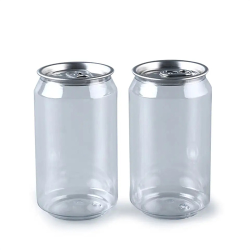
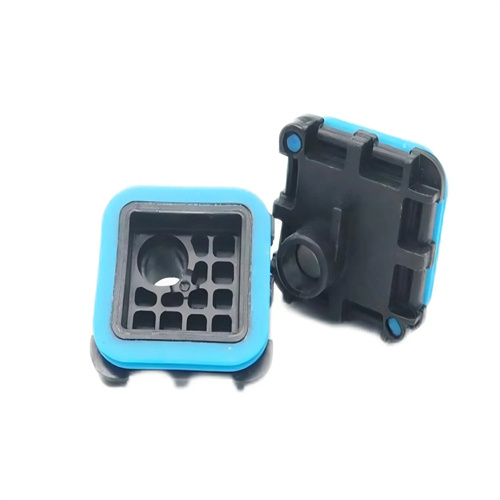
Depending on the part’s structure, dual-ejection mechanisms can be categorized into various types, each with its own application scenarios. The push plate-ejector combination is suitable for cups and cylinders. An integral push plate is used on the fixed mold side for demolding, while an ejector is used on the movable mold side. For example, in a yogurt cup mold, the push plate first pulls the cup’s rim out of the cavity, and the ejector then pushes the cup’s base to release it from the core. The pull plate-bevel ejector combination is suitable for parts with internal grooves. The pull plate on the fixed mold first pulls the part out of the cavity, while the bevel ejector in the movable mold simultaneously pulls the core laterally, releasing the inner groove. This is an example of a mold for a mobile phone case with a buckle. The rack-and-pinion combination uses a gear transmission to achieve simultaneous demolding from both sides. It is suitable for symmetrical parts (such as round lids) that require even force on both sides, ensuring deformation-free operation. For example, when producing a 200mm diameter round plastic lid, a rack-and-pinion drive is used to synchronize the push plates on both sides, keeping demolding force deviation within 5% and reducing lid flatness error from 0.3mm to 0.1mm.
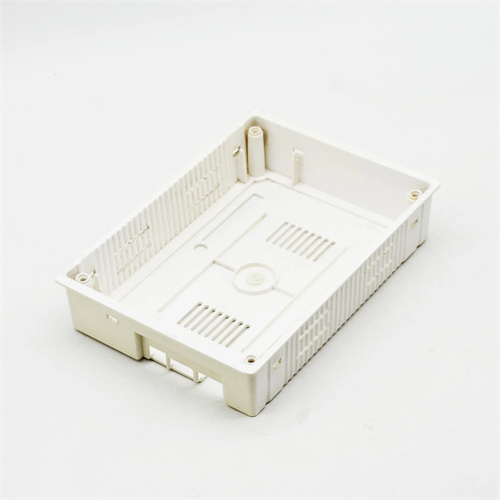
Common problems and solutions for dual-ejection mechanisms require special attention during design and debugging. If interference occurs (such as collision between the fixed mold ejector plate and the movable mold ejector pin), the limit dimensions must be readjusted to ensure that the driven system’s stroke is smaller than the active system, or a delay device (such as a throttle valve in the cylinder oil circuit) must be added to control the sequence of movements. If the plastic part is retained on the cavity side, it is often due to insufficient ejection force on the cavity side. The spring specifications can be increased (such as from a Φ8mm spring to a Φ10mm spring) or the ejector plate area can be increased. If the part is retained on the core side, the core surface finish must be improved (Ra ≤ 0.8μm) or the number of ejectors must be increased. For deformation of the plastic part after demolding, it is necessary to check whether the ejection force on both sides is balanced. Pressure sensors can be installed on the ejector plate and ejector plate to monitor the force deviation in real time and adjust it to within ±5%. For example, when debugging the double-demolding mechanism of a cosmetic box, the box body warped due to excessive force from the fixed mold push plate. By replacing the small elastic spring and reducing the pre-demolding stroke from 15mm to 10mm, the deformation was reduced from 0.5mm to 0.1mm.