Injection molding inclined top side core pulling mechanism
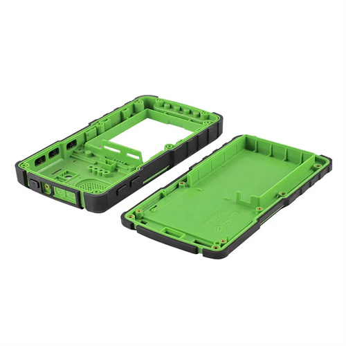
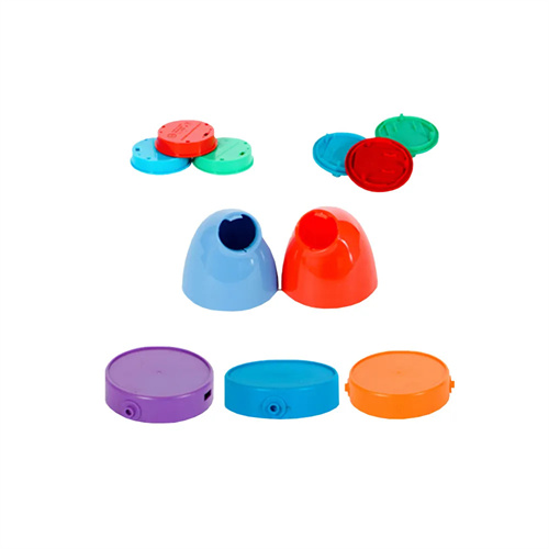
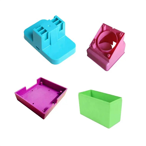
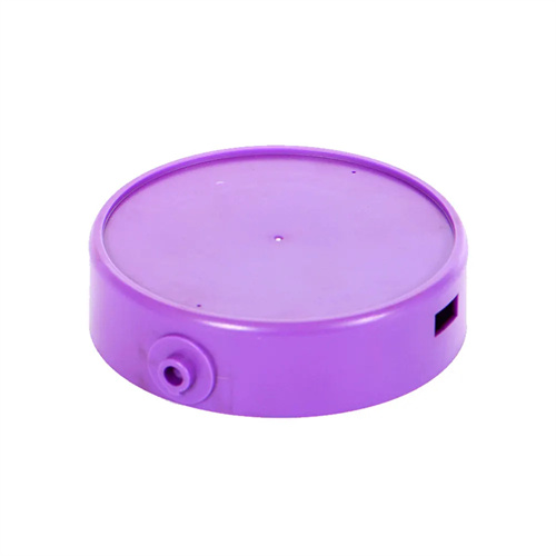
The lateral core-pulling mechanism for injection molding is a crucial device for demolding parts with internal undercuts or complex curved surfaces. By tilting the ejector rod, it simultaneously performs lateral core-pulling operations while ejecting, combining both ejection and core-pulling functions. It is widely used in the production of plastic parts with internal grooves, such as mobile phone casings and medical devices. Compared to traditional lateral core-pulling mechanisms, this mechanism requires no additional power source for core-pulling, instead utilizing the ejection motion during mold opening to simultaneously perform core-pulling. This makes it more compact and particularly suitable for small molds with limited space. For example, when producing cosmetic bottle caps with internal annular grooves, the lateral core-pulling mechanism can simultaneously move outward and away from the groove during ejection, eliminating the interference issues associated with traditional core-pulling mechanisms and improving demolding efficiency by over 40%. Furthermore, this mechanism’s smooth core-pulling action effectively reduces ejection marks on the part surface, improving product appearance quality.
The composition and working principle of the injection molding lateral core-pulling mechanism are fundamental to understanding its function. The mechanism primarily consists of a lifter, a guide seat, an ejector plate, a return spring, and a stop block. The lifter is the core actuator, with its lower end connected to the ejector plate and its upper end in contact with the undercut on the inside of the plastic part. The rod has a certain inclination angle (usually 8°-15°). The guide seat is fixed to the movable mold base plate and contains a guide hole aligned with the inclination angle of the lifter, providing precise guidance for the lifter’s movement. The ejector plate moves upward during mold opening, driving the lifter to move diagonally along the guide hole. The return spring is used to pull the lifter back to its initial position during mold closing. The stop block limits the lifter’s maximum ejection distance to prevent excessive movement. The working process is as follows: when the mold is opened, the ejector plate moves upward under the drive of the ejection mechanism, and the inclined ejector rod, constrained by the guide seat, produces a composite upward and lateral movement at the same time. The upward movement realizes the ejection of the plastic part, and the lateral movement completes the core pulling of the inner side under the inverted buckle; when the ejection reaches the set position, the plastic part is completely separated from the core and the inclined ejector rod; when the mold is closed, the return spring pulls the inclined ejector rod downward with the ejector plate, resets along the guide seat, and the stop block ensures that it returns to the precise initial position, waiting for the next molding.
The structural design of the lifter pin is crucial for ensuring effective core pulling and requires precise design based on the undercut characteristics of the plastic part. The cross-sectional shape of the lifter pin must match the shape of the undercut inside the plastic part. Common shapes include rectangular, circular, and irregular. For complex curved undercuts, the upper end of the lifter pin must be contoured to ensure a tight fit with the part, achieving a fit of at least 90%. The length of the lifter pin is calculated based on the ejection distance and the tilt angle using the formula L = H / sin α + K, where L is the lifter pin length (mm), H is the ejection distance (mm), α is the tilt angle, and K is the length of the connecting portion at each end (typically 20-30mm). For example, for a 50mm ejection distance and a 10° tilt angle, the lifter pin length is approximately 50/sin 10° + 25 = 287 + 25 = 312mm. The material of the lift rod must have high strength and wear resistance. Cr12MoV or SKD61 is usually selected. After heat treatment, the hardness reaches HRC50-55 and the surface roughness Ra≤0.8μm to reduce friction resistance during movement.
The design of the guide seat and reset mechanism is crucial to the stability of the mechanism’s motion. The guide hole in the guide seat and the lifter rod adopt an H7/f7 clearance fit, with a clearance of 0.01-0.03mm. The hole axis’s inclination angle must be perfectly aligned with the lifter rod, with an error of no more than 0.5°. Failure to do so can cause the lifter rod to stall or wear. The guide seat is made of 45 steel, tempered to a hardness of HB220-250. The internal guide hole is precision-ground to a surface roughness of Ra ≤ 0.4μm. The reset mechanism typically uses a cylindrical coil spring. The spring force is determined based on the lifter rod’s weight and resistance to movement, typically 1.5-2 times its weight, to ensure reliable reset during mold closing. The spring should be installed close to the lifter rod to avoid generating additional torque. The spring’s free length should be 20%-30% longer than its compressed working length to ensure sufficient preload. Furthermore, a solid lubricant, such as molybdenum disulfide, can be added between the guide seat and the lifter rod to reduce friction and wear.
Common problems and solutions for the lateral core-pulling mechanism of the inclined ejector are important guarantees for ensuring stable production. Common problems in production include: jamming of the inclined ejector rod, which is mostly caused by too small a clearance between the guide hole and the inclined ejector rod or deviation in the tilt angle, requiring re-grinding of the guide hole or adjustment of the angle; scratches on the inside of the plastic part, usually due to insufficient surface roughness of the inclined ejector rod or poor fit with the plastic part, requiring improvement of the surface polishing accuracy of the inclined ejector rod or optimization of the contour design; deformation or breakage of the inclined ejector rod, mostly due to insufficient material strength or excessive force, requiring replacement of high-strength materials or reduction of the tilt angle. During debugging, it is necessary to gradually adjust the ejection speed and observe whether the movement of the inclined ejector rod is smooth and whether the core pulling is thorough. Red lead can be applied to the inclined ejector rod to check the contact with the plastic part to ensure uniform contact. Through reasonable design and careful debugging, the service life of the lateral core-pulling mechanism of the inclined ejector rod can reach more than 500,000 molds, meeting the needs of mass production.