Considerations for mold arrangement for multi-cavity injection molding
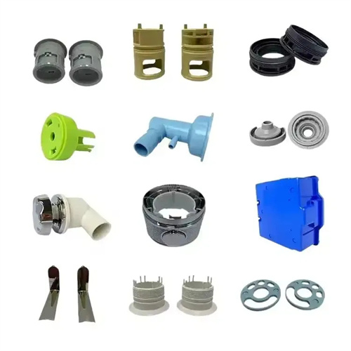
Injection molds with multiple cavities produce multiple parts in a single injection molding cycle, significantly improving production efficiency and reducing unit product costs. They are widely used in the mass production of small plastic parts such as bottle caps and electronic connectors. However, the layout design of multi-cavity molds is complex. Improper layout can lead to uneven filling of each cavity, significant variations in part quality, and even shortened mold life due to uneven force. For example, when producing a 16-cavity mobile phone button mold, improper layout can cause the weight of each button to vary by more than 8%, making assembly difficult. Therefore, the layout of multi-cavity molds requires comprehensive consideration of factors such as the number of cavities, distribution, and runner design, adhering to scientific design principles to ensure consistent part quality across cavities.
Determining the number of cavities requires balancing production efficiency and part quality, and is a primary step in mold placement design. The number of cavities should be determined based on the injection molding machine’s parameters (maximum shot size, clamping force, platen size) and the part’s dimensional accuracy requirements. Regarding maximum shot size, the total cavity weight (including the part and runners) should not exceed 80% of the machine’s maximum shot size to avoid underfilling. Regarding clamping force, the force should be greater than the product of the cavity’s projected area and the injection pressure to prevent flashing. For example, if the machine’s maximum shot size is 200g and the clamping force is 500kN, if each part weighs 5g and the runner weighs 20g, a maximum of 30 cavities can be configured ((200 x 80% – 20) / 5 = 30). Furthermore, the number of cavities should be an even number (e.g., 2, 4, 8, or 16 cavities) to facilitate symmetrical arrangement. For parts requiring high precision, the number of cavities should be limited, generally no more than 32, as this will make it difficult to ensure uniform filling across the cavities.
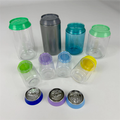
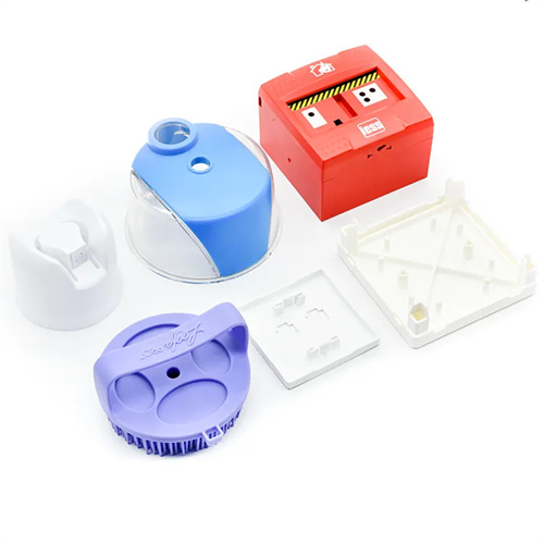
The cavity distribution must adhere to the principle of symmetry and balance to ensure consistent filling conditions across cavities. Common distribution patterns include circular radial, rectangular matrix, and linear symmetry. Circular radial distribution is suitable for a large number of cavities (eight or more). Each cavity is evenly distributed around the sprue, with a uniform flow path length and minimal fill time variation. For example, a 16-cavity bottle cap mold using this method can keep the fill time variation within 0.1 second. A rectangular matrix distribution is suitable for rectangular parts or those requiring automated part removal. The cavities are neatly arranged in rows and columns, facilitating the placement of cooling waterways and demolding mechanisms. For example, an 8-cavity mobile phone battery case mold uses a 2×4 matrix distribution with uniform spacing between cavities. A linear symmetry distribution is suitable for elongated parts. The cavities are symmetrically arranged along the sprue . For example, a 4-cavity penholder mold uses this method, with completely symmetrical cavities on the left and right sides. Regardless of the distribution pattern, the distance from each cavity to the sprue should not vary by more than 5% to ensure consistent melt flow resistance.
The runner system must be designed to match the cavity layout to ensure even melt distribution. The main runner should be located in the center of the mold, concentric with the injection molding machine nozzle. Its diameter is determined by the nozzle size and is generally 4-10mm. The branch runners must be balanced, meaning that the length, cross-sectional shape, and dimensions of the branch runners from the main runner to each cavity are identical, ensuring that the melt reaches each gate simultaneously. The diameter of a circular branch runner is typically 5-12mm, with the smaller diameter being used for small parts and the larger diameter for large parts. For example, in an 8-cavity mold, branch runners radiate from the main runner, with each branch having identical length and diameter to ensure even melt distribution. The gates should be uniformly positioned and sized. For symmetrically distributed cavities, the gates should be located at the same location, with a dimensional tolerance of no more than 0.05mm. Furthermore, the transitions at the branch runners should be rounded to reduce pressure loss. A cold well should be located at the end of the branch runner to prevent cold slug from entering the cavity and affecting part quality.
The design of the cooling system and demolding mechanism must be coordinated with the cavity layout to ensure consistent conditions across all cavities. Cooling water channels should be evenly distributed around each cavity, maintaining a distance of 15-25mm from the cavity and a channel diameter of 8-12mm. For multi-cavity molds, either series or parallel water channels can be used. Circular cavities are well-suited to circular series water channels, ensuring uniform cooling time for each cavity. Matrix-shaped cavities are well-suited to parallel water channels, with independent water supply to each row of cavities to ensure uniform flow. For example, a 16-cavity mold using a circular water channel can maintain a temperature differential within ±1°C and minimize shrinkage differences within 0.5%. Regarding the demolding mechanism, components such as ejector rods and ejector tubes must be aligned with each cavity and positioned symmetrically to ensure uniform demolding force across all cavities. For molds with automatic demolding, the cavity layout must consider where the plastic parts will fall after ejection to prevent collisions. Staggered arrangement or the provision of guide plates can be used to guide the plastic parts as they fall. For example, the matrix-distributed cavity adopts staggered ejection to disperse the falling positions of the plastic parts, making it easier to remove them automatically.

Mold strength and manufacturing process considerations are practical requirements for cavity arrangement. The distance between cavities must be sufficiently large to ensure mold strength and processing space. For small plastic parts, the cavity spacing should be no less than 10-15mm, and for large parts, no less than 20-30mm. Too small a spacing can lead to localized mold strength deficiency and deformation under clamping force. The distance between the cavity and the mold edge should be no less than 25-30mm to prevent edge cracking. For example, when producing a 20mm diameter part, a cavity spacing of 15mm and an edge distance of 30mm can keep mold deformation under clamping force to within 0.01mm. Regarding manufacturing process, cavity arrangement should be symmetrical whenever possible to reduce processing time. For example, circular cavities can be machined in a single pass using an indexing head, improving processing accuracy and efficiency. Complex arrangement requires design and programming using CAD/CAM software to ensure consistent cavity dimensions and positional accuracy within 0.02mm. By comprehensively considering these factors, the production efficiency of a multi-cavity mold can be increased several times while ensuring the consistency of plastic part quality.