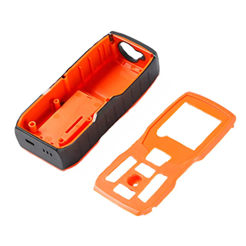
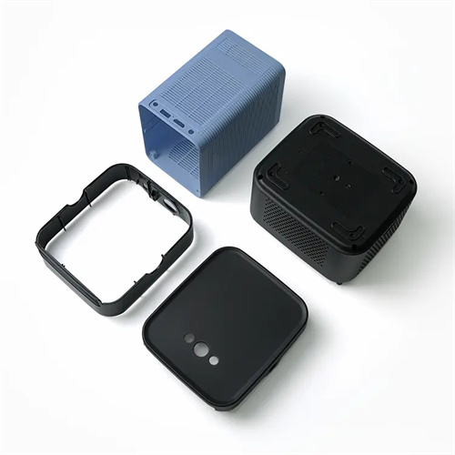
Warping (deformation) and solutions
Warpage (deformation) in injection molded parts refers to the unintended bending, twisting, or buckling of a molded part after cooling. It’s a common defect that affects product dimensional accuracy and is particularly prominent in thin-walled, elongated, or asymmetrical parts. The underlying cause is uneven internal stress within the part. When this stress is released, the part deforms in the direction of less stress. For example, rectangular polypropylene sheets often warp upward on all four sides after molding. This occurs because the edges cool faster than the center, constraining contraction at the edges and creating tensile stresses that ultimately cause the edges to warp upward to relieve the stress. Warpage not only affects product assembly performance —for example, causing snap-on misalignment and unacceptable flatness—but can also reduce the mechanical strength of the part due to stress concentration, shortening its service life.
The core causes of warpage require in-depth analysis from three perspectives: material properties, mold design, and molding process. Crystalline plastics (such as polyethylene and polyoxymethylene) experience significant volume changes during crystallization. Uneven cooling can easily lead to differences in crystallinity, which in turn causes warpage. Reinforced materials (such as glass-reinforced nylon) can also deform due to differential shrinkage due to inconsistent fiber orientation. Mold design flaws are also crucial, such as improper gate placement leading to asymmetric melt flow paths, uneven cooling system distribution resulting in significant differences in cooling rates across the part, or insufficient draft angles leading to forced deformation during demolding. Improper process parameters can directly exacerbate warpage, such as excessive injection pressure leading to excessive molecular chain orientation, insufficient holding time leading to uneven shrinkage, and excessively short cooling time leading to premature part release. For example, in the production of ABS plastic cover panels, cooling water channels were only installed on one side of the mold, resulting in a cooling rate difference of up to 20°C on both sides of the cover panel. This ultimately resulted in warpage, with the panel bending toward the side without the cooling channels, exceeding 0.5mm.
To address material issues, the shrinkage and orientation properties of the material must be controlled at the source. For crystalline plastics, adding nucleating agents can refine the crystal grains and reduce crystal volume variation. For example, adding 0.2-0.5% sorbitol-based nucleating agents to polypropylene can achieve a more uniform crystallinity distribution and reduce warpage by over 30%. Selecting low-shrinkage grades is also an effective approach. For example, when producing precision gears, POM with a shrinkage of 1.0-1.2% is preferred over the 1.5-2.0% of standard grades. For reinforcement materials, fiber length and content must be controlled. Short fibers (0.1-0.3mm in length) disperse more evenly than long fibers, minimizing orientation variations. Excessive fiber content (over 30%) increases anisotropy and should be adjusted to 15-25% based on product requirements. Furthermore, pre-drying the material to prevent moisture from affecting crystallization or causing degradation can also indirectly reduce warpage.
Optimizing mold design is a key step in addressing warpage, focusing on achieving uniform cooling and balanced flow. The cooling system should be evenly distributed according to the part’s shape, ensuring that the temperature difference between different parts is within 5°C. For example, large flat parts should use multiple sets of parallel water channels, with spacing no more than 50mm, and the distance between the channel wall and the cavity surface maintained at 15-20mm. The gate should be set to ensure symmetrical melt flow paths. Center gates or multi-point symmetrical gates are preferred to minimize flow orientation differences. For example, using diagonal double gates for rectangular parts allows the melt to fill symmetrically from both sides, reducing orientation stress. Increasing the draft angle (1°-2° for crystalline plastics and 0.5°-1° for amorphous plastics) can reduce demolding resistance and avoid plastic deformation caused by forced demolding. For areas prone to warping, the mold can be configured with anti-deformation compensation, such as a preset reverse slope based on the warping direction, to allow the part to naturally correct after cooling. For example, when producing PVC window frames, based on the inward warping phenomenon found during the trial mold, an outer anti-deformation slope of 0.3° is preset in the mold cavity, and the flatness of the final product is controlled within 0.2mm/m.
Warpage can be effectively mitigated by adjusting process parameters, requiring precise control based on the warpage type. For warpage caused by molecular orientation, the injection speed and pressure should be reduced to minimize molecular chain alignment. For example, the injection speed can be reduced from 80 mm/s to 50 mm/s, and the injection pressure from 120 MPa to 90 MPa. The barrel temperature should also be appropriately increased to reduce melt viscosity and minimize shear orientation. For warpage caused by uneven cooling, the cooling time should be extended to ensure that all parts of the part are fully formed. For example, the cooling time for thick-walled parts should be no less than 30 times the wall thickness (mm to seconds). The mold temperature should also be raised to near the material’s glass transition temperature (e.g., PC mold temperature should be controlled between 100-120°C) to reduce internal stress. Optimizing holding pressure parameters is also crucial. Using staged holding pressure (high pressure initially to maintain shape, low pressure later to compensate for shrinkage)—for example, holding pressure at 80% of the injection pressure for the first 5 seconds and then decreasing to 50% for the last 5 seconds—can achieve more uniform shrinkage. For example, when producing nylon 66 bearing seats, insufficient holding pressure caused excessive shrinkage in the center and warping. By extending the holding time from 8 seconds to 12 seconds and increasing the holding pressure from 70MPa to 90MPa, the warpage was reduced from 0.8mm to 0.2mm.