Injection molding inclined surface precise positioning mechanism
The precise positioning mechanism for injection molding’s inclined surface alignment is a key device for ensuring precise alignment between the mold cavity and core. It’s particularly suitable for molds for large, complex plastic parts. Through the guiding and positioning effects of the inclined surface, the mold alignment error can be controlled within 0.01-0.03mm, significantly improving the dimensional accuracy of the plastic part. Compared to traditional guide pin and guide bushing positioning, the inclined surface alignment mechanism offers advantages such as high positioning accuracy, strong load-bearing capacity, and automatic clearance compensation. It is widely used in the production of demanding plastic parts such as automotive bumpers and instrument panels. For example, when producing automotive door panels exceeding one meter in length, the use of the inclined surface alignment mechanism can reduce the alignment error between the left and right molds from the traditional 0.1mm to 0.02mm, effectively avoiding flash and dimensional deviations, and increasing product qualification rates by over 25%.
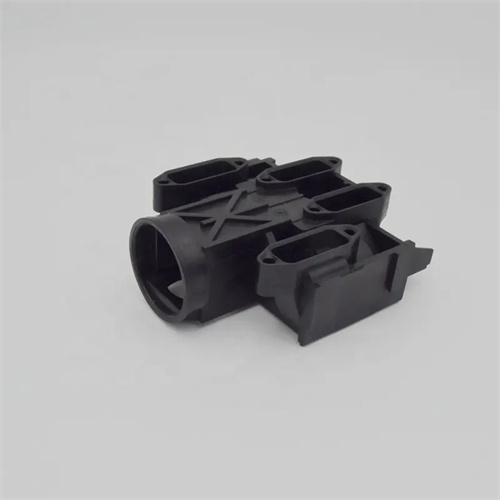
The composition and working principle of the injection molding bevel alignment precision positioning mechanism are key to understanding its function. This mechanism primarily consists of a bevel locating block, a bevel insert, a hold-down spring, and an adjustment shim. The bevel locating block is fixed to the fixed mold side, with its working surface being a precisely machined bevel, typically with an inclination of 10°-30°. The bevel insert is installed in the corresponding position of the movable mold, with its bevel angle aligned with the locating block to ensure a tight fit. The hold-down spring maintains contact between the locating block and the bevel insert before mold closing, providing preload. The adjustment shim fine-tunes the position of the bevel insert to ensure alignment accuracy. The working process is as follows: when closing the mold, the movable mold moves toward the fixed mold, and the inclined surface of the inclined positioning block first contacts the inclined surface insert of the movable mold. Under the guiding action of the inclined surface, the movable mold will produce a slight lateral movement, automatically compensating for the position deviation between the two molds; as the mold closing continues, the two inclined surfaces fit tightly together, relying on the wedge effect of the inclined surfaces to achieve precise alignment; after the mold closing is completed, the mold generates a huge positive pressure between the inclined surfaces under the action of the clamping force, further ensuring the stability of the positioning; when the mold is opened, the compression spring pushes the inclined surface insert to reset, waiting for the next mold closing.
The angle and precision of the chamfer are key parameters for ensuring effective positioning. The selection of the chamfer angle β requires a comprehensive consideration of positioning accuracy and locking force. An angle that is too small (less than 10°) will result in a weak guiding effect and difficulty compensating for large positioning deviations. An angle that is too large (greater than 30°) will increase the required locking force and increase mold load. Generally speaking, for high-precision positioning applications, a chamfer angle of 10°-15° is recommended, which provides high guiding sensitivity and minimizes positioning errors. For large molds or applications requiring greater locking force, an angle of 20°-30° can be used to reduce clamping force consumption. The machining precision of the chamfer must be extremely high, with a surface roughness of Ra ≤ 0.02μm, a flatness error of no more than 0.005mm/m, and a parallelism error of less than 0.01mm between the two chamfers to ensure gap-free assembly. Furthermore, the effective contact length L of the chamfer should be determined based on mold size and is generally no less than 50mm. For large molds, the contact length can be increased to 100-200mm to ensure sufficient positioning stability.

The installation, fixing, and adjustment methods of the mechanism significantly impact positioning accuracy. The bevel locating block is secured to the fixed mold using both screws and pins. High-precision cylindrical pins (tolerance h6) are used as pins, and the positioning error of the locating holes should not exceed 0.01mm to ensure the installation accuracy of the bevel locating block. The bevel insert is connected to the movable mold using a floating structure, with fine adjustments achieved via springs and adjustment shims. The thickness of the adjustment shims has an accuracy of 0.001mm. The position of the bevel insert can be fine-tuned by adding or removing shims to keep the gap between the two bevels within 0.005mm. During installation, a dial indicator or laser interferometer is used to check the relative position of the bevels to ensure they align perfectly parallel when the mold is closed. For large molds, at least four sets of bevel alignment mechanisms are required, distributed at the four corners of the mold to form a symmetrical layout to avoid positioning deviations caused by unilateral force.
Maintaining the accuracy of the bevel alignment mechanism is crucial for long-term stable operation. During daily production, the bevel surface should be regularly cleaned of impurities such as oil and plastic debris to prevent them from affecting fitting accuracy. Cleaning should be done gently with a soft cloth dipped in anhydrous ethanol to avoid scratching the bevel. Regularly inspect the bevel for wear. The contact area can be measured using a color-coating method. If the contact area is less than 80%, the bevel should be polished to restore its flatness and roughness. The compression spring should be regularly checked for force loss. If the spring length decreases by more than 5%, it should be replaced promptly to ensure stable preload. After mold repair or component replacement, the accuracy of the bevel alignment mechanism should be recalibrated, and the alignment error should be restored to within 0.01mm by adjusting the shims. Furthermore, during mold design, a temperature compensation device can be incorporated near the bevel to minimize the impact of thermal deformation caused by temperature fluctuations on positioning accuracy. With these measures, the bevel alignment mechanism can maintain high-precision positioning over the long term, meeting the demands of high-volume, high-quality plastic part production.