Main parameters of injection molding inclined ejector mechanism
The performance of the injection molding ejector mechanism depends on the proper design of a series of key parameters, which directly affect the core-pulling effect, motion stability, and plastic part quality. As the core device for demolding complex plastic parts, the ejector mechanism’s parameter design must take into account multiple factors, including core-pulling distance, ejection height, and stress conditions. Any unreasonable parameter can lead to mechanism jamming, plastic part deformation, or mold damage. For example, an excessively large tilt angle may cause the ejector to experience a sharp increase in stress and break, while a too small tilt angle will not meet the core-pulling distance requirements; insufficient ejection height will prevent the plastic part from being fully demolded, while excessively high ejection height may cause mechanism interference. Therefore, a thorough understanding and precise determination of the key parameters of the ejector mechanism is a prerequisite for ensuring the proper operation of the mold and product quality.
The tilt angle is a crucial parameter of the lifter mechanism, directly determining the core-pulling distance and the magnitude of the applied force. The tilt angle α is the angle between the lifter axis and the vertical, typically ranging from 5° to 15°, with a maximum value of 20°. An angle that is too small (less than 5°) results in insufficient core-pulling distance, making complete core-pulling impossible, especially with deep undercuts. An angle that is too large (greater than 20°) dramatically increases the lateral force on the lifter, leading to increased wear on the guide seat and even bending and fracture of the lifter. Experimental data shows that increasing the tilt angle from 10° to 20° increases the lateral force on the lifter by approximately three times. In practical designs, the tilt angle should be determined based on a combination of the core-pulling distance and ejection height. If the core-pulling distance is S and the ejection height is H, then α = arctan (S/H). The calculated angle should be rounded to the nearest reasonable value. For example, when the core pulling distance is 10mm and the ejection height is 60mm, α=arctan (10/60)≈9.46°, and 10° can be taken in actual design.
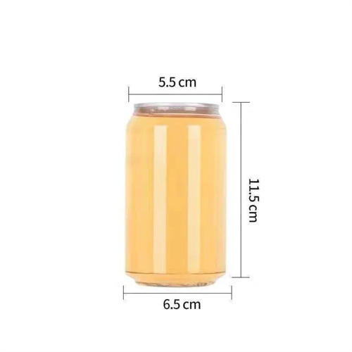
The core-pulling distance and ejector height are key parameters in determining the length of the ejector pin. The core-pulling distance, S, refers to the lateral movement required by the ejector pin to free the part from the undercut. This distance should be greater than the undercut depth, typically 1-2mm greater, to ensure complete core extraction. For example, if the inner undercut depth of the part is 5mm, the core-pulling distance should be 6-7mm. The ejector height, H, refers to the vertical distance the ejector pin travels to eject the part from the core. This distance must ensure smooth part removal and is typically 1.1-1.3 times the part’s height. For larger parts, the ejector height can be increased. The relationship between the core-pulling distance and ejector height must satisfy S = H × tanα. These three parameters are interrelated and require comprehensive consideration during design. If the core-pulling distance and tilt angle are known, the ejector height can be calculated using the equation H = S / tanα. If the ejector height is limited by the mold structure, the core-pulling distance can be calculated using S = H × tanα to determine if the required distance is met. Adjust the tilt angle if necessary.
The cross-sectional dimensions and length of the lifter are crucial parameters for ensuring its strength and rigidity. The lifter’s cross-sectional dimensions must be determined based on the load it bears. The width b and thickness h of a rectangular cross-section can be calculated using the bending strength formula: b ≥ (6F L) / (σ b h²), where F is the lateral force (N) borne by the lifter, L is the cantilever length (mm), and σ is the allowable bending stress (MPa) of the material. Common cross-sectional dimensions are 10-25mm in width and 8-20mm in thickness. For applications with higher loads, the cross-sectional dimensions can be increased or a circular cross-section (10-30mm in diameter) can be used. The lifter’s total length, L, is comprised of the cantilever length (L) and the connection lengths at both ends. The cantilever length is the distance from the guide seat to the top of the lifter and is generally not to exceed 300mm. Excessive lengths can result in insufficient rigidity and may cause bending deformation. High-strength alloy tool steel, such as Cr12MoV, should be used, achieving a hardness of HRC50-55 after heat treatment to ensure sufficient strength and wear resistance.
Guide clearance and reset accuracy are critical parameters affecting the smoothness of the mechanism’s movement. The clearance between the lifter and the guide seat must be strictly controlled. Too small a clearance (less than 0.01mm) will increase resistance to movement and even cause jamming. Too large a clearance (greater than 0.05mm) will cause the lifter to wobble during movement, affecting core pulling accuracy. A typical clearance is 0.02-0.03mm, using an H7/f7 tolerance. The guide hole should be no less than 3-5 times the lifter diameter to ensure guiding accuracy. Reset accuracy refers to the flushness between the lifter tip and the core surface after mold closing. The tolerance should be controlled within ±0.02mm, otherwise a step or depression will be left on the part surface. To ensure reset accuracy, a reliable reset device is required, such as a high-strength spring (5-10mm diameter, 30-50mm free length) or a reset lever for forced reset. In addition, the surface roughness of the inclined ejector rod must reach Ra≤0.8μm, and the surface roughness of the guide hole of the guide seat must reach Ra≤0.4μm to reduce movement friction and increase the service life of the mechanism.