Injection molding push block specifications, materials and heat treatment
Injection molding push blocks are important components for demolding complex plastic parts. Their specifications, material selection, and heat treatment process directly affect the demolding effect and service life. Push blocks are typically used to mold bosses, ribs, or irregular surfaces of plastic parts. They need to fit tightly with the surface of the plastic part to provide uniform demolding force, so their specifications must be precisely matched to the plastic part structure. If the push block is too large, the mold volume and cost will increase; if the specifications are too small, it will not provide sufficient demolding force, resulting in deformation or damage to the plastic part. For example, when producing automobile bumper parts with large bosses, the push block must be large enough to cover the entire boss area and be thick enough to ensure rigidity. Otherwise, it will bend due to excessive force during demolding, affecting the dimensional accuracy of the plastic part.
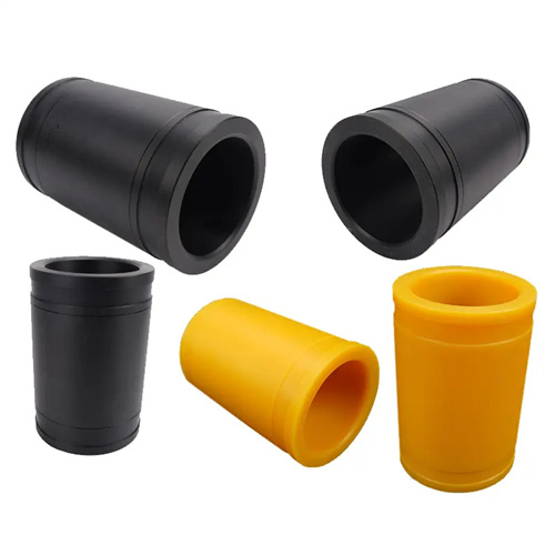
The pusher block’s specifications, including size, shape, and mounting method, must be designed specifically based on the characteristics of the plastic part. The working surface of the pusher block should be slightly larger than the part being pushed, typically 0.5-1mm larger per side, to ensure complete coverage of the demolding area. The thickness of the pusher block is determined based on the demolding force, typically ranging from 10-30mm. For larger pusher blocks, the thickness can be increased to 40-50mm, and reinforced ribs should be provided to enhance rigidity. The pusher block’s shape must conform to the contact area of the plastic part. For curved parts, the working surface of the pusher block must be contoured to achieve a fit exceeding 95% to avoid excessive localized stress. There are two mounting methods: fixed and floating. Fixed pushers are directly screwed to the pusher plate and are suitable for applications with stable demolding forces. Floating pushers utilize a spring connection to the pusher plate, adapting to even the slightest surface deformation of the plastic part and suitable for demolding high-precision parts. For example, a floating mounting method is used for pusher blocks in mobile phone cases, effectively preventing ejection marks caused by slight deformation of the case.
The selection of pusher block materials requires a comprehensive consideration of wear resistance, strength, and processability. Common pusher block materials include carbon tool steel, alloy tool steel, and high-speed steel. Carbon tool steels such as T10A are inexpensive and offer excellent processability, but they suffer from poor wear resistance and hardenability. They are suitable for small-batch production of plastic parts with low requirements. After heat treatment, their hardness can reach HRC 50-55. Alloy tool steels such as Cr12MoV offer high wear resistance, strength, and good hardenability, making them suitable for large-scale production or for forming parts with complex surfaces. After heat treatment, their hardness can reach HRC 58-62, resulting in a service life 3-5 times that of T10A. High-speed steels such as W18Cr4V offer excellent wear resistance and are suitable for forming parts with reinforced materials such as glass fiber, effectively resisting wear. However, due to their difficulty and high cost in processing, they are only used in specialized applications. For example, when producing PA66 parts containing 30% glass fiber, pusher blocks made of Cr12MoV can extend their service life by more than four times that of T10A.
The heat treatment process of pusher blocks plays a decisive role in their performance, and appropriate process parameters must be determined based on the material’s characteristics. For T10A pusher blocks, the heat treatment process is as follows: heating to 780-800°C, holding for 30-40 minutes, water quenching, and then tempering at 180-200°C for 2 hours, achieving high hardness and a certain level of toughness. The heat treatment process for Cr12MoV pusher blocks is more complex, requiring staged heating: preheating at 600-650°C for 2 hours, then heating to 850-880°C and holding for 1-2 hours, and finally heating to 1020-1050°C and holding for 30-40 minutes, oil quenching, and then tempering at 200-220°C three times, each for 2 hours, to ensure a uniform martensitic structure and achieve a hardness of HRC 58-62. After heat treatment, pusher blocks require low-temperature aging to eliminate internal stresses and prevent deformation during use. For example, after aging treatment, the deformation of the Cr12MoV push block can be controlled within 0.01mm/m, ensuring the fitting accuracy with the plastic part.
Surface treatment and precision control of the pusher block are complementary measures to ensure its performance. Nitriding can be used for surface treatment, creating a 0.1-0.2mm hardened layer on the working surface of the pusher block, increasing its hardness to HV800-1000. This significantly enhances wear resistance and reduces surface roughness to Ra ≤ 0.4μm, reducing friction with the plastic part during demolding. For pusher blocks with demanding requirements, polishing can be performed to achieve a mirror-like finish on the working surface to prevent scratching the plastic part. Regarding precision control, the pusher block’s dimensional tolerance must be controlled within ±0.01-±0.02mm, with a flatness error no greater than 0.01mm/m. The clearance between the pusher block and the pusher plate must be 0.01-0.03mm to ensure smooth movement. Prior to assembly, the pusher block undergoes rigorous testing using a coordinate measuring machine to check dimensional accuracy and form tolerances to ensure compliance with design requirements. Through appropriate specification design, material selection, and heat treatment, the pusher block’s service life can be extended to over 500,000 cycles, meeting the demands of high-volume production.