Overflow (flash, burr) and its solution
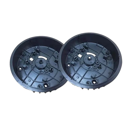
Flash (also known as burr or flash) is one of the most common defects in injection molding. It manifests as excess, thin flakes of plastic at the edge or parting surface of a plastic part. This not only affects the product’s appearance but can also cause assembly difficulties, dimensional deviations, and, in severe cases, even damage the mold. Flash occurs primarily when pressure at the mold parting surface or gap exceeds the clamping force, causing the melt to overflow through the gap. For example, in the production of ABS plastic housings, flash can increase the housing’s edge thickness by 0.1-0.3mm, making it impossible to assemble with other components and resulting in a scrap rate of 10%-20%. Flash is associated with a variety of factors, including insufficient clamping force, low mold precision, and inappropriate process parameters. Effectively controlling this defect requires targeted solutions.
Insufficient or unevenly distributed clamping force is one of the main causes of flash. When the actual clamping force of the injection molding machine is less than the required clamping force, a slight gap will form on the mold parting surface due to the melt pressure, allowing the melt to overflow and cause flash. The formula for calculating the required clamping force is: Clamping force = Projected area of the part × Injection pressure × Safety factor (1.2-1.5). For example, for a part with a projected area of 500 cm² and an injection pressure of 100 MPa, the required clamping force = 500 × 100 × 1.2 = 6000 kN. If the injection molding machine clamping force is only 5000 kN, flash is likely to occur. Uneven clamping force distribution can also cause localized flash. For example, large mold parallelism errors and uneven force on the tie rods can cause excessive gaps on the parting surface. Solutions include: selecting an injection molding machine with sufficient clamping force to ensure the actual clamping force exceeds the required value; adjusting the mold adjustment mechanism to keep the mold parallelism error within 0.05mm/m; and checking the tightness of the tie rods to ensure uniform force across all four. For example, by calibrating the tie rods to keep the elongation difference within 0.02mm, localized overflow can be effectively resolved.
Mold precision and clearance are key factors in preventing flash. Excessive flatness errors (exceeding 0.01mm/m) and high surface roughness (Ra>0.8μm) on the mold parting surface can lead to loose fit and the formation of micro-gaps. Excessive clearance between the mold cavity and core (exceeding 0.03mm), or between the guide pin and guide bushing, can cause the mold to shift under injection pressure, resulting in flash. For example, if the clearance between the guide pin and guide bushing exceeds 0.05mm, the mold parting surface will be misaligned, resulting in noticeable flash. Solutions include: improving the machining accuracy of the parting surface, controlling the flatness error within 0.005mm/m and the surface roughness to Ra≤0.4μm; reducing the clearance between the cavity and core to 0.01-0.02mm, and adopting an H7/h6 tolerance for the guide pin and guide bushing; and regularly cleaning the parting surface to remove impurities such as plastic debris and oil to ensure a tight fit. For example, after fine grinding and polishing of the parting surface, the occurrence rate of flash can be reduced by more than 50%.
Improper process parameter settings are a major cause of flash. Excessively high injection pressure increases the force exerted by the melt on the mold, exceeding the clamping force and causing flash. For example, the injection pressure for PC material is typically 80-120 MPa. Missetting it to 150 MPa significantly increases the risk of flash. Excessively high injection speeds can cause turbulence in the melt within the cavity, leading to localized pressure surges and pulsed pressure shocks, which can cause localized flash. Excessively high barrel temperatures can reduce melt viscosity, increasing melt fluidity and making it more likely to overflow through gaps. Solutions include: appropriately reducing the injection pressure (the lower the better, while ensuring full fill), gradually reducing the pressure through trial molds until flash-free and complete fill is achieved; employing multi-stage injection speeds, starting with a slow initial injection speed to avoid sudden pressure increases; and rationally setting the barrel temperature to reduce it within the material’s tolerances. For example, reducing the temperature for PC material from 300°C to 280°C can reduce flash. For example, by reducing the injection pressure from 120MPa to 100MPa and simultaneously reducing the injection speed by 20%, the flash defect rate can be reduced from 15% to 3%.
The impact of raw material properties and melt fluidity on flash should also not be ignored. Different plastics have significantly different fluidities. Plastics with good fluidity (such as PE and PP) are more prone to flash than plastics with poor fluidity (such as PC and POM) because their low melt viscosity makes it easier for them to overflow through tiny gaps. Excessive low-molecular volatiles or moisture in the raw material can generate gas during the injection process, increasing pressure within the mold cavity and indirectly causing flash. Solutions include: For plastics with good fluidity, appropriately lowering the barrel temperature and injection pressure and increasing the mold temperature to accelerate cooling; thoroughly drying the raw material, especially for highly hygroscopic materials such as PA and PC, with a moisture content controlled below 0.05%; and judiciously adding fillers, such as adding 10%-20% calcium carbonate to PE, to reduce its fluidity and minimize flash. For example, the flash rate of PA66 raw materials can be reduced by 40% after thorough drying.

Dynamic control and mold maintenance during the production process are long-term measures to prevent flash. A comprehensive mold inspection is required before production, including parting surface fit, guide mechanism clearance, and venting slot dimensions to ensure compliance. During production, the clamping force should be regularly checked for stability. This can be monitored in real time using the injection molding machine’s pressure sensor. If clamping force fluctuates by more than 5%, adjustments should be made promptly. For multi-cavity molds, ensure uniform filling of each cavity to avoid localized pressure increases caused by overfilling a cavity. After a period of use, the parting surface should be reground to remove burrs and scratches, and worn guide pins and bushings should be replaced to restore fit accuracy. For example, comprehensive mold maintenance after every 100,000 production runs can keep the flash defect rate below 2% for a long period of time. Furthermore, implementing an online inspection system that automatically identifies flashed parts through machine vision and provides timely feedback to adjust process parameters, creating a closed-loop control system, can further improve flash control.